![]()
CS 548 - Robot Motion Control and Planning
Term Project: Modeling and Control of a Spherical Mobile Robot
Ali Nail İNAL
Bilkent University, Electrical & Electronics Engineering Department
Instructor: Asst. Prof. Uluç SARANLI
Introduction
As the term project of the Robot Motion Control and Planning course, we intended to model a nonholonomic nonlinear mobile robot platform named Ballbot, shown in fig. 1. By using this dynamic model of the robot, we will to control the system. This system is important, since Ballbot can move to any direction in any. It uses only a ball to move, and it stabilizes itself on the ball. Although there are models that can stabilize on a wheel and football (american) , they can only move to restricted directions, like front and back. This makes Ballbot the ideal mobile robot platform for the indoor human environment. System will be described in the following section.
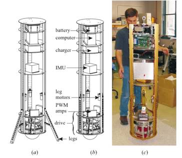
Figure 1: Ballbot system [2]
System
Description
The system chosen for this project is a mobile robot
platform, Ballbot. Ballbot is an omnidirectional, mobile robot that dinamically
stand on a urethane-coated metal
sphere[1]. Body of the robot is a cylinder, as tall as a human, it moves using
the inverse of the computer mouse principle, uses 2 or 4 motor (on different
versions) to drive the ball in coordinate axes, shown in Fig.2.
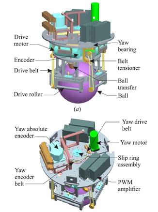
Figure
2. Inverse Mouse-ball
Drive of the Ballbot
We will use a simplified model of
the robot that consist of a ball and a cylindrical body located on it for the
project. In this model, body can freely move on the ball, like an inverted
pendulum,shown in Fig.3. Ball and the body are rigid and there is no slip
between ball and the floor. Friction between ball and floor, and ball and the
body are modeled as viscous damping. Static friction and nonlinear dynamic
friction are neglected[3]. In
the previous dynamic modeling work done on the robot, by Lauwers, Kantor and
Hollis, median planes are assumed to be decoupled and equations of motion for
both planes are identical [5]. This way they separated the motion in two axis
directions, and use this to model robot’s motion.
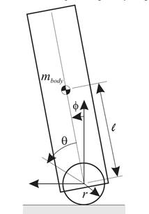
Figure 3: Simplified
Ballbot Model [5]
Unlikely to the previous model, we will calculate the
system’s motion of equations as a hole in both directions. Since, there is an
independent motor for yaw axis motion, we will not include the yaw axis to this
model. This way, our states will be ![]() . We will use Lagrangian to calculate the equations
of motion, by writing energy equations;
. We will use Lagrangian to calculate the equations
of motion, by writing energy equations;
![]()

We
obtained the Lagrangian of the system as ![]() . Then using Lagrange method, we obtained the
equations of motion as
. Then using Lagrange method, we obtained the
equations of motion as
![]()
![]()
where, ![]() is the moment of inertia of the body
about the center of the ball,
is the moment of inertia of the body
about the center of the ball, ![]() is the distance between the center of the ball
and the center of mass of the body,
is the distance between the center of the ball
and the center of mass of the body, ![]() is the mass of the body,
is the mass of the body, ![]() is the moment of inertia, mass and radius of
the ball, respectively. Their values are given in the following table [4].
is the moment of inertia, mass and radius of
the ball, respectively. Their values are given in the following table [4].
Table 1. System Parameters
|
Parameter |
Symbol |
Value |
|
Z-axis CM from ball
center |
|
0.69 m |
|
Ball radius |
|
0.106 m |
|
Ball inertia |
|
0.0174 kgm2 |
|
Ball mass |
|
2.44 kg |
|
Roll moment of inertia
about CM of body |
|
12.59kgm2 |
|
Pitch moment of inertia
about CM |
|
12.48kgm2 |
|
Yaw moment of inertia
about CM |
|
0.66kgm2 |
|
Body mass |
|
51.66 kg |
|
Viscous Damping friction
coefficient |
|
0.17 Mms/rad |
Thus, system is defined
as,
As it can be seen from equations, this
system is nonlinear and nonholonomic. It may be a problem for the controller
design as it is discussed in the following section.
Linear Controller Design
For this project, we hope to control the
system above with a linear controller. For this reason we linearize the system
for body angles, around zero this way we can obtain a linear controller using
pole matching control method. After linearization, using the mentioned contleer
method we design a controller and obtained the following results for the
controller with simple feedback.
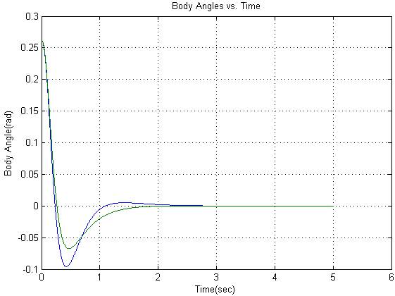
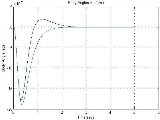
Figure 4: (a) Linear control output of body angles
for 15 degree initial state (b) Linear control output of body angles for 0
degree initial state
As it can be seen they are stable with good timing for different initial state
but for bigger angles the stabilization time and peak values are bigger with
logarithmically .
Implementation and Results
After controlling the systems body angles, in order to find position of the robot, we use quaternions and obtained the position of the system better, since this is a nonholonomical system, we use the following two equations for the position estimation, x and y velocities of the system
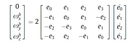
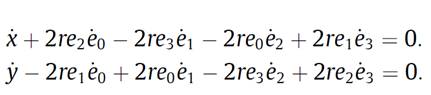
Figure 4: (a) Angular velocity quaternion relation (b) Velocity, quaternion relation [4]
Using these relations, we obtain the position of the robot by integrating the velocities of the robot. Some of the results are given in the following:
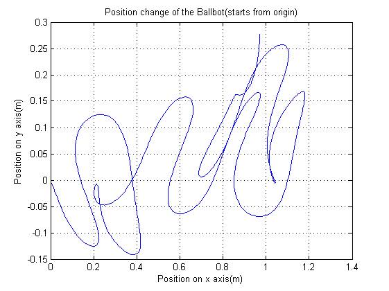
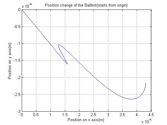
Figure 5: (a) position
estimation with 15 degree initial state (b) position estimation with 0 degree initial
state
As it can be seen if the body angles are larger, there will be problem with the position stabilization, for this we hope to use another controller to stabilize it over velocities.
Conclusion
Our main goal in this assignment is to control this system with the model we create for the ballbot system. It gives us the results we hope to get. However, if the controller is chosen as a nonlinear one the results would be better, and using quaternion is a good choice for the position control that we hope to do in near future.
References
[1] Carnegie Mellon Researchers Develop New Type of Mobile Robot That Balances and Moves on a Ball Instead of Legs or Wheels(n.d.). Retrieved April 10,2010 from Carnegie Melon Robotics Institute Web site: http://www.msl.ri.cmu.edu/projects/ballbot/text/BallbotAugustFinal.pdf
[2] T.B. Lauwers, G.A. Kantor and R.L. Hollis, “One is Enough!”, in Proc. Int’l. Symp. for Robotics Research, October 12-15, 2005.
[3] T.B. Lauwers, G.A. Kantor and R.L. Hollis, “A dynamically stable single-wheeled mobile robot with inverse mouse-ball drive”, in Proc. IEEE Int’l. Conf. on Robotics and Automation, 2006, pp 2884-2889.
[4 ] Joshi V.A., Banavar, R.N., Hippalgaonkar R., “Design and analysis of a spherical mobile robot”, Mechanism and Machine Theory, vol.45, 2010,pp 130-136
[5] Umashankar Nagarajan, Anish Mampetta, George Kantor and Ralph Hollis, “State Transition, Balancing, Station Keeping, and Yaw Control for a Dynamically Stable Single Spherical Wheel Mobile Robot”, Proc. IEEE Int’l. Conf. on Robotics and Automation, May 2009.