Walfisch- Bertoni Model
Walfisch –Bertoni model, called
also as diffracting screens model [1], is a semi -deterministic model valid for
situations uniform building heights and spacing. The model approach the buildings
as absorbing diffracting edges and finds the field strength at low grazing
angles at what field is settled to a value. Further simplification is made by
assuming an elevated fixed antenna achieved by using the local plane wave
approximation to calculate the influence of buildings on field strength on the
spherical wave radiation by elevated antenna.
(1)
The model firstly finds the
amplitude Q(a) of the field at roof tops
due to a plane wave of unit amplitude incident at the glancing angle a on a number of buildings. It is found that
for large number of buildings, Q(a) settles to a constant
value. Then, this value is multiplied by following factor (1) to find the field
amplitude at the mobile.

(2)
where
ho is the average height of the buildings in meters , b is center to
center distance between two successive buildings in meters and g is given by following
formula 2. and g and a are in radians.
![]()
Furthermore,
formula 1 is simplified to 1/(g-a) by assuming that a is small compared to g.

Figure 1[1] Geometry for Walfisch-Bertoni Model
The
geometry for the model is given in figure above. From the figure it is easily
found that
(3)
![]()
sina=H/R where H =hb-ho.
For small a values, this expression
gives a=H/R, by the inclusion of
earth’s curvature effect yields
where
Re is effective earth radius and Re=8.5x10³
km.
![]()
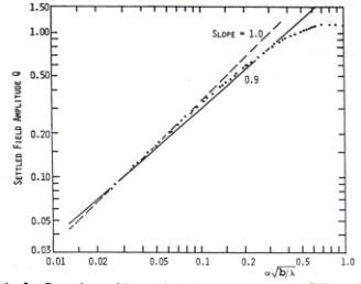
Dependence of the field amplitude on parameter aÖ(b/l) is found by calculating
the settled field amplitude for values of aÖ(b/l) from 0.01 to 1.0. The
obtained figure is given below 2.
(4)

Solid line is used as
a fit to the settled field, thus with a in radians following
formula is found for amplitude of field strength:
This
is valid for 0.02<aÖ(b/l)<0.5.
By
multiplying equation simplified version of 1 with 3 yields field strength value
at mobile unit with respect to one unit field strength radiated by transmitter.
Decibel expression of the multiplication yields excess path loss Lex
formula proposed by the model.
(5)


Summation of Lex and free space loss
gives the total path loss Lo
(6)
Lo=Lex+LFS
A comparison of the model with measurements is done in
[1]. Figure 3 shows a comparison of the model with measurements carried out at
Philadelphia for different H values at 820 MHz. In measurement data although
range dependence is about 36.8 dB, model gives 38 dB range dependence, which is
a sufficient result.

Figure 3[1] Comparison of sector-averaged signal strength for various transmitter sites, with theoretical predictions (solid lines). Signal level is in dBm, range in miles, H in meters.
Also, [1] gives a comparison of the model with
okumura curves by the sight of a. Plot of excess attenuation
as a function of the a is given figure 4.

Figure 4 [1] Comparison of excess path loss found from theoretical model (solid
curve) with measurement of Okumura plotted as a function of the a at
f=922MHz and transmitter heights of 45 m and 140 m.
The plot shows that excess
attenuation for both transmitting antenna heights agree with in 3 dB. This
agreement means that excess path loss is a function of a rather than of R and H.
A comparison of the model
with Hata model is given by the following figure taken by using Wireless
Simulator output.
Terrain Parameters: Average Width: 73.8 m Average Building Height: 10.63m Percentage of Buildings: 37% Study Parameters: Frequency: 900 MHz, TX Height (hb)=50m Mobile Height (hm)=1.5m TX Gain: 13 dBi City Size: Small/Medium Area Type : Suburban

Figure 5 Comparison of the Walfisch-Bertoni Model
with Okumura –Hata Model.
In this study, average
building height is taken to be 10.6 m, which is a height of typical house
with 3 floor and a roof in a suburban. The path loss value at 4.96 km
for the model is 120.78 dB whereas that value is 123.88 dB for Hata model. This
study implies that propagation takes place over the buildings, with diffraction
of the rooftop fields down to the mobile [2].
In the literature,
comparison of the model with measurements carried out in different cities [3]
are done and it is shown that model is not applicable for large values of parameter
v= aÖ(b/l) greater than 0.5. In [3], for v=1, error >3 dB and for v=2 error>6dB are
observed. Actually, the amplitude of field strength Q(a) in 2.2.2.3 is approximated from curve in
figure 2 and it is mentioned that the 3
is more accurate for v<0.5.
(7)
This
model can be considered as the limiting case of the flat edge model when the
number of buildings is sufficient for the field to settle, i.e. n ³ ns [4] where
![]()
Use
of Walfisch –Bertoni model is limited to case that large number of buildings
are present and particularly grazing angle a is small. Also, it should
be cared that model is valid for H>0 as seen in formula 4. That means model
works when base station antenna height is above the average rooftop level.
[1] J.Walfisch and H.L. Bertoni, “ A Theoretical model of UHF propagation in urban environments,” IEEE Trans. Antennas Propagat., vol.36, 1988, pp.1788-1796
[2] H.L.Bertoni, “Radio Propagation for Modern Wireless Systems”,Prentice Hall,New Jersey, USA,200
[3] N.Cardona, P.Moller, and F.Alonso, “Applicability of Walfisch-type urban propagation models”, Electron.Letts., Vol.31,1995, pp.1971-1972
[4] Sounders, Simon.R., “ Antennas and Propagation for
Wireless Communication Systems”,Wiley,New York,1999