Directional couplers have usually less coupling factor.
To increase the coupling between lines, very thin and close lines are
required which is not possible. One idea to increase the coupling is
to use several lines parallel to each other. In this way, the
fringing fields contribute to the coupling. Lange coupler is an practical
example of this. This coupler can easily achieve 3 dB coupling ratios.
The main disadvantage of Lange coupler is the lines
are very narrow and it is difficult to fabricate bonding wires across the
lines.
The unfolded Lange coupler operates as the original Lange coupler (figure2). It is easier to model with an equivalent circuit. Unfolded Lange coupler can be modelled as 4 line when we consider that each line couples only to its nearest neighbour.
If we derive even and odd characteristics impedance
of four lines in terms two line even and odd impedances we can use the
coupled line coupler results.
This relation is
![]() ,
,
From 
Voltage coupling factor can be written as
![]()
If we derive Zoe and Zoo in terms of Zo and C
These results are not very precise because we used two line approximations to the four line approximations and also assumed that even and odd mode phase velocities are equal. However, these results give sufficient accuracy in practice.
Using found Zoo and Zoe impedances geometry ratios, w/h and s/h, can be determined for microstrip layout (fig 2) as usual.
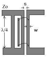
figure 2: unfolded Lange Coupler