


Previous: Safety
Next: Experiment 1: Reflection, refraction, and optical power
Subsections
The opto-mechanical equipment in the laboratory provide a system for
holding, positioning, aligning, rotating, and translating optical
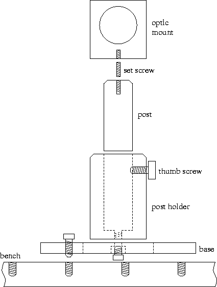
components. The figure shows a typical arrangement of opto-mechanical
components aimed at positioning an optic on the optical bench. Please
note that the opto-mechanical equipment in the laboratory have
dimensions and standards that are mostly in English units; i.e. they
are not metric.
There are two boxes with a variety of screws. Two
different thread sizes exist for the screws: 1/4-20 (large diameter) and
8-32 (small diameter). (Some optical mounts have 6-32 size set
screws as well.) Cap screws have a head and a hex socket. Set screws
do not have heads. Allen wrenches and ball drivers are used with the
hex sockets.
A wrench set with different size Allen wrenches are provided. Always
be careful to use the correct size wrench. Otherwise, the tip of the
wrench may be damaged. Do not over-tighten any screws. A controlled
amount of torque is usually enough to secure a screw.
The optical bench provides a platform for positioning the optical
components used in the experiments. The bench has threaded holes
in a rectangular array with 1 inch (2.54 mm) spacing. The threads are
for 1/4-20 screws.
Bases are either screwed directly to the optical bench, or secured
with a clamp. Short bases are available in situations where space is
limited.

Post holders are screwed to the bases. They can hold a 1/2 inch thick
post at an adjustable height. The thumb screws on the post holders are
used to secure the post at the desired height. Do not over tighten
the thumb screw. Post holders can also be screwed onto the rotation
platform and the translation stage. Six post holders are available at
two different heights.
Posts are steel rods with threaded holes on either side. One side has
1/4-20 threads, and the other side has 8-32 threads. These threads
are used to connect the post to an optic holder or mount with a set
screw. After this, the post goes into the post holder.
There are 12 posts of various sizes available for each group.
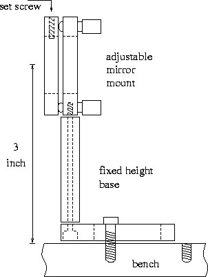
There are four fixed-height bases for 3 inch and one for 2 inch beam
heights. Adjustable mirror mounts are connected to these fixed height
bases as shown in the figure with long 8-32 screws from the bottom.
There are a variety of mounts for holding different optical components:
- Adjustable mirror mount (4): These mounts are for holding 1 inch
optics. The pitch and yaw angles can be adjusted using the knobs at
the back. The optic is secured in its position with a nylon tipped set
screw.
- Small adjustable mirror mount (2): These mounts are for holding
1 inch optics. The optic is placed in a metal holder which is then
secured to the mount with a set screw. In the experiments these mounts
are used to hold the mirrors that steer the laser beam.
- Plate holder (1): This is used to hold thick optical
components. Be careful not to tighten the retaining screw too much, as
this may damage the optical component.
- Slide holder (2): These are used to hold optical components that
are mounted in slide frames. Be careful while inserting the slides
into the holder.
- Fixed optic mount (3): These mounts hold 1 inch optics with
little mechanical obstruction, but have no adjustments.
- Threaded optic holder (4): These are used to hold optical
components that are mounted in cylindrical threaded housings, such as
the lenses in the lens set.
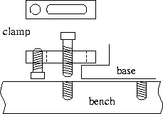
Clamps are used to secure the bases on to the optical bench. Using
clamps allows more freedom in the positioning of bases. Clamps are
used as shown in the figure.
The XZ translation stage provides accurate linear motion in two
dimensions. The micrometers on the translation stage provide distance
readings in 10  m increments. The total range of the micrometers is
25 mm.
m increments. The total range of the micrometers is
25 mm.
Two rotation stages provide calibrated angular motion around an axis
that is parallel to the beam. One of the stages is dedicated to the
42 mm diameter polarizers.
The rotation base provides calibrated angular motion around an axis
that is perpendicular to the beam.
The angle measurement rotation base provides both calibrated angular
motion and a mechanism for measuring the angle of a reflected beam.
This base is used with magnetic component holders.
A variable iris serves as a variable diameter circular aperture.
Irises are also useful as alignment tools and to block unwanted stray
reflections. Be careful not to force the iris at the smaller end of
its diameter range.
The right angle post clamp can be used to connect two posts at right
angles.
A steel ruler with both mm and inch units can be used for measuring
distances up to 15 cm.
The Helium-Neon laser produces an intense beam of light. Observe the
safety precautions outlined on page ![[*]](cross_ref_motif.gif) at all times to
avoid injury.
at all times to
avoid injury.
The Helium-Neon laser operates at a wavelength of 632.8 nm. Its
output power is nominally 0.8 mW. The beam has a Gaussian
(TEM ) transverse profile and is linearly polarized. The He-Ne
laser has a power supply with an on/off switch and indicator light on.
) transverse profile and is linearly polarized. The He-Ne
laser has a power supply with an on/off switch and indicator light on.
The laser takes some time to warm up after first being turned
on. (Approximately 15 minutes.) The output power level may fluctuate
during this time. At the beginning of the experiment, make sure that
the laser is properly mounted before turning it on. Leave the laser on
throughout the experiment. Use an opaque object to block the
beam when not in use.
Four dielectric mirrors and two aluminum mirrors with flat surfaces
are provided. The dielectric mirrors are broadband visible mirrors
designed to be used at 0-45 incidence angle. An additional
aluminum mirror mounted on a magnetic mount is also provided.
incidence angle. An additional
aluminum mirror mounted on a magnetic mount is also provided.
A set of lenses that are mounted in cylindrical threaded housings is
provided. There are fourteen positive and two negative lenses in the
set.
Two polarizing filters are provided. These have rotating threaded
housings that fit one of the rotation stages.
The half-wave and quarter-wave waveplates (retarders) operate at
633 nm.
A 50% dielectric beamsplitter operating at visible wavelengths is
provided. The beamsplitter is designed to work at 45 incidence
angle.
A blank glass plate that has the same dimensions as the beamsplitter
provides a method to compensate for the thickness of the beamsplitter
in an interferometer.
A green monochromatic light source is provided.
The incandescent light source is a regular light bulb. The bulb
filament temperature is 2700 K. The spectrum of the emitted
light is that of a blackbody radiator at this temperature. The light
source has an on/off switch on the back panel. There is a knob on the
top to align the bulb filament.
The power meter is used to measure the light power. It consists of a
silicon photodiode, an amplifier with different scales, and a readout
from a volt meter. A He-Ne filter can be used to block the room
lights when measuring laser light. Be sure to turn off both the volt
meter and the detector when you are done using the power meter.
The diffuser provides a means of obtaining diffuse light. It can be
used both with the laser and the incandescent light source.
The crossed arrow target has perpendicular arrows of different widths
with a circle concentric on the crossing points of the arrows. The
larger arrow contains a 15 mm scale.
A number of slits with varying slit number, width, and spacing are
provided. It may be necessary to use a mask on the opposite
side of the component carrier to insure that light is incident on only
one pattern at a time.
Two circular apertures with different diameters and two special
diffraction patterns are provided. It may be necessary to use a
mask on the opposite side of the component carrier to insure
that light is incident on only one pattern at a time.
Circular opaque points and two Fresnel zone plates are provided. The
two zone plates are complementary; the opaque zone of one is the
transparent zone of the other. It may be necessary to use a
mask on the opposite side of the component carrier to insure
that light is incident on only one pattern at a time.
A transmission type diffraction grating with 5276 lines/cm is
provided.
A 6 mm thick glass plate is provided.
A 19 mm thick acrylic plate is provided. Acrylic plate is softer
than glass and is scratched more easily.
A 90 -45-45 glass prism is provided.
An aluminum concave spherical mirror (50 mm radius of curvature,
25 mm focal length) is provided.
A viewing screen with a metric scale is provided for measurements.
The aperture mask is used to block unwanted patterns on multiple
pattern components such as slits and diffraction patterns.
Circular apertures are provided to be used in front of light sources.
The water tank is 90 mm in diameter and 50 mm in depth.
A transmission type hologram is provided.
Previous: Safety
Next: Experiment 1: Reflection, refraction, and optical power
Orhan Aytür