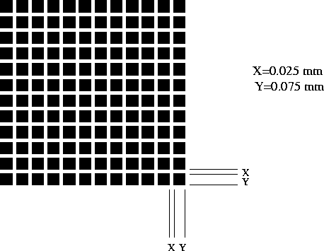
Calculate the far field intensity distribution for the pattern
shown in the figure. Assume a unity amplitude where there is a dark
square and zero amplitude elsewhere. The pattern can be
mathematically represented as a properly scaled rectangle function
multiplied by an array of smaller rectangle functions as
![\begin{displaymath}
f(x) = \mbox{rect} \left[ \frac{x}{12(X+Y)} \right] \sum_{q=...
...infty}
\mbox{rect} \left[ \frac{x-(q-1/2)(X+Y)}{Y} \right] .
\end{displaymath}](img86.gif)

Expand the laser beam with a Galilean telescope (![]() mm and
mm and
![]() mm). Make sure that it is well collimated. Mount the pattern
on a slide holder and position it at the center of the beam. The
central portion of the Gaussian beam approximates a plane
wave. Observe the intensity of the field as it propagates after the
pattern. Describe how the intensity distribution changes as the field
propagates. Observe the intensity distribution in the far
field. Compare this distribution (quantitatively) with your
calculations.
mm). Make sure that it is well collimated. Mount the pattern
on a slide holder and position it at the center of the beam. The
central portion of the Gaussian beam approximates a plane
wave. Observe the intensity of the field as it propagates after the
pattern. Describe how the intensity distribution changes as the field
propagates. Observe the intensity distribution in the far
field. Compare this distribution (quantitatively) with your
calculations.
It is possible to take the inverse transform by placing another
![]() mm lens at a distance of one focal length from the Fourier
plane, thus setting up a 4-
mm lens at a distance of one focal length from the Fourier
plane, thus setting up a 4-![]() system. However, this will produce an
output signal that is difficult to inspect with the naked
eye. Instead, you can let the light distribution at the Fourier plane
propagate to the far field, as in the previous part, thus taking the
inverse transform. Observe that the output signal is a scaled up
version of the input signal when there is no filter in the Fourier
plane.
system. However, this will produce an
output signal that is difficult to inspect with the naked
eye. Instead, you can let the light distribution at the Fourier plane
propagate to the far field, as in the previous part, thus taking the
inverse transform. Observe that the output signal is a scaled up
version of the input signal when there is no filter in the Fourier
plane.
In all of the steps below, draw space domain and frequency domain
diagrams to explain the filtering process. Mount a slide holder onto
the XZ translation stage such that different filters can be positioned
accurately at the Fourier plane. Position the 0.5 mm slit in the
Fourier plane at the center of the light distribution. What type of
filter is this? What is the effect of the filter on the output
signal? Replace with the 0.2 mm slit and compare. Rotate the filter by
90![]() and compare. Using your results from part 1, calculate
the fundamental spatial frequency of the periodic variation of the
input signal. Which one of the apertures filters out this frequency
component?
and compare. Using your results from part 1, calculate
the fundamental spatial frequency of the periodic variation of the
input signal. Which one of the apertures filters out this frequency
component?
Position the 0.5 mm circular aperture at the center of the transform. What type of filter is this? What is the effect of the filter on the output signal?
Position the 0.25 mm opaque point at the center of the transform. What type of filter is this? What is the effect of the filter on the output signal? Replace with the 0.5 mm point and compare.
The laser beam will be expanded with a Galilean telescope (![]() mm
and
mm
and ![]() mm). An object slide will be placed after the collimating
lens. A
mm). An object slide will be placed after the collimating
lens. A ![]() mm lens will be positioned at a distance of one focal
length from the signal plane. Examine the light distribution at the
Fourier plane, one focal length from the lens. Observe that the far
field intensity is a scaled up version of the object intensity when
there is no filter in the Fourier plane. The assistant will place
various filters in the image plane (on a translation stage). Note
the changes in the output.
mm lens will be positioned at a distance of one focal
length from the signal plane. Examine the light distribution at the
Fourier plane, one focal length from the lens. Observe that the far
field intensity is a scaled up version of the object intensity when
there is no filter in the Fourier plane. The assistant will place
various filters in the image plane (on a translation stage). Note
the changes in the output.